2 SSMC Topology Insights

HPE 3PAR & Primera SSMC Topology Insights

Hello, starting with SSMC 3.6, HPE introduced a new feature called topology Insights.

Let me introduce what topology Insights is and how to enable it.

This guest post is brought to you by Armin Kerl, if you fancy trying you hand at blogging check out our guest posting opportunities.

What is SSMC Topology Insights?

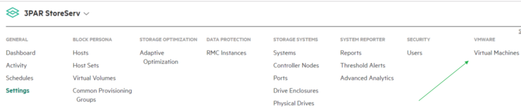
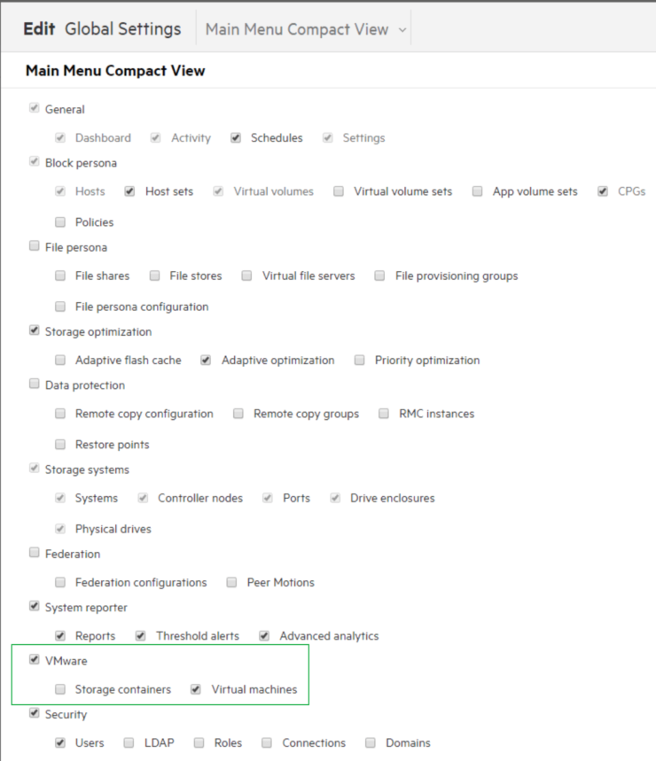
Topology Insights allows a consolidated view of both storage and the VMware layer.  To see it within SSMC go to: VMWARE > Virtual Machines

1 SSMC Menu

Change to: Topology view from the drop down in the right hand window

2 SSMC Topology Insights

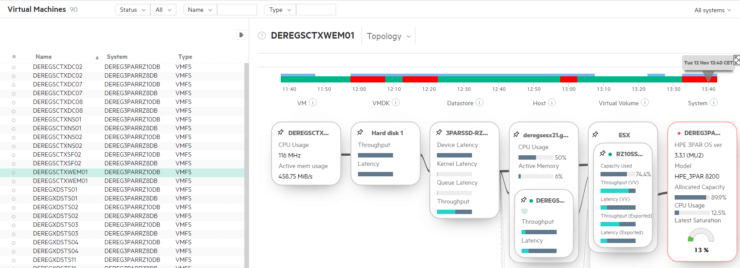
You will see all VM’s and the relationship between:

VM <> VMDK <> Datastore <> ESXi Server <> Virtual Volume <> Storage

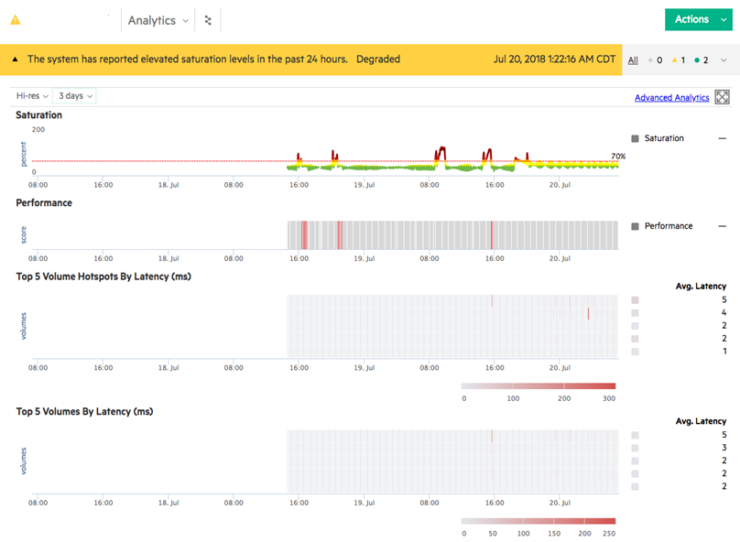
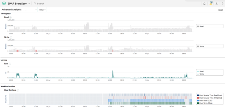
Also, any performance impacts are displayed on top with a selectable time line, red shows a problem.

How to get Topology Insights?

You need at least:

  • SSMC 3.6
  • 3PAR with OS 3.3.x
  • Service Processor 5.x
  • VMware vCenter (no Hyper-V currently)

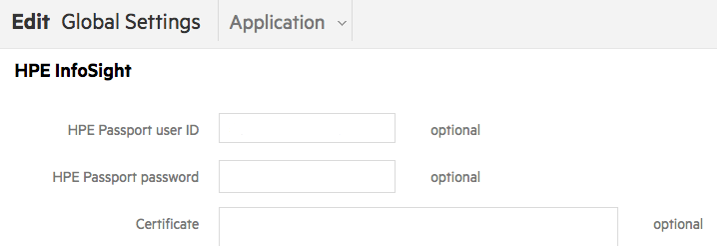
In the SSMC go to Settings

3 SSMC Settings

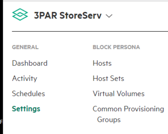
In Section “Application” enable “Topology”

4 Enable Topology Insights

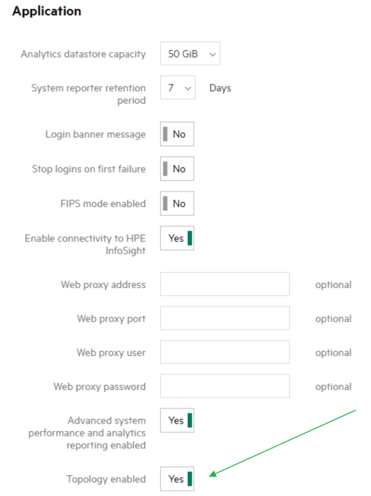
and VMware > Virtual machines

5 SSMC Settings

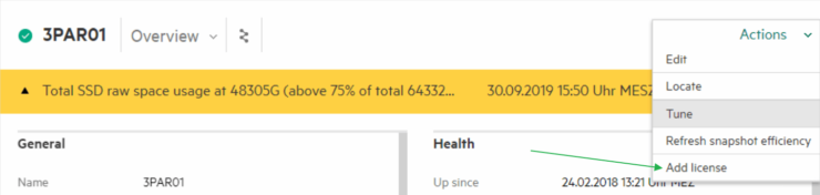
Now go to “Storage Systems” > “Systems” > “Actions”

6 Set SP credentials

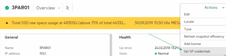
Enter the “Set SP credentials” here.

If it is successful, check under “Systems” > “Settings” if the vCenters entry is here.

7 Add vCentre

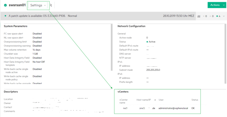
If not, go to edit and enter here.

If you don’t see “Set SP credentials”?

Like this:

8 Missing Set SP credentials

Or get this Message?

9 Missing service processor

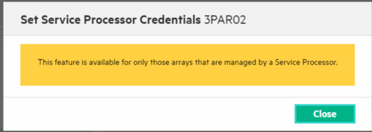
I have had several customer sites, where the entry did not appear.

Most of the time these are storage systems and SP, which have been upgraded from 3.2.x to 3.3.x.

The following is for information only, it is recommended to contact support before proceeding.

It is a little bit Tricky, but here is a way to fix it:

Login to the 3PAR with SSH (Putty).

Enter: cli% getsys -showsysobjs

Look for {ServiceProcessorCookie {}}

Wrong: … {SessionTimeout 10800} {ServiceProcessorCookie {}} …

Right: … {SessionTimeout 10800} {ServiceProcessorCookie SPxxxyyyyzzzz:IP.of.the.SP}

If the SP Cookie is empty “{}”, we need to fix it.

Login to the SP 5.x Website and go to the Service Processor Overview Homepage.

10 Service processor values

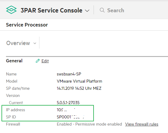
Here we see the SPIP = IP address and SPID = SP ID

Now set the missing Values:

cli% setsys ServiceProcessorCookie SPID:SPIP

Example: setsys ServiceProcessorCookie SPCZ123456789:192.168.10.23

Check again: Enter: cli% getsys -showsysobjs

Now OK?

Go back to the SSMC and the “Set SP credential” should appear.
This fix worked for me every Time.

Thank you, folks for reading.

Armin

3PAR Saturation

3PAR SSMC 3.4 – What’s New ?

HPE have just released SSMC 3.4, it looks like a small update, but it brings a big change and many new features. Therefore, I would say the right Version should be 4.0.

This guest post is brought to you by Armin Kerl, if you fancy trying you hand at blogging check out our guest posting opportunities.

What’s New in SSMC 3.4?

The key new features in SSMC are:

  • Appliance Deployment – Now a Linux based appliance VM
  • New Setup Sizing Guidelines – Small, large or medium deployments available depending on the number of 3PAR systems you are managing
  • InfoSight Integration – Tighter integration with InfoSight
  • Performance Analytics – Includes simplified reporting indicating if system is overstretched or performing well
  • Replication – Enhancements to management

Let us get a deeper look at the new features:

Download SSMC

To get the latest 3.4 version of SSMC you can download it from the HPE Software Depot. Once downloaded you will find an ISO with the name format HPESSMC-.iso. When you mount the ISO you will find the appliance image file in there HPE_SSMC__VMware_Image plus the migration tool (HPE_SSMC__Migration_Tool) which will allow you to migrate your current settings to the new appliance.

SSMC Appliance

In the Past, we installed the SSMC as a service on an existing Windows or Linux Host, now it is a standalone Linux based appliance. Today supported operating systems to run the appliance on are VMware ESXi version 6.0, 6.5, 6.7 or Microsoft Hyper-V Server 2012 or 2016. The 3PAR OS can be 3.2.1, 3.2.2 or 3.3.1.

SSMC Deployment

During the Deployment you can choose the initial settings like IP address and you can choose between three Sizing Options:

SSMC 3.4 Deployment

Small

Use the Small deployment option to manage up to 8 arrays and 128K objects. This deployment needs 4 vCPUs, 16GB memory and min 500GB Disk Space.

Medium

With the Medium deployment option, you can manage up to 16 arrays and 256K objects. This deployment needs 8 vCPUs and 32GB memory and min 500GB Disk Space.

Large

The large deployment option allows management of up to 32 arrays and 500K objects. This deployment needs 16 vCPUs and 32GB memory and min 500GB Disk Space.

SSMC Migration

If you are already running SSMC 3.2 or 3.3, you can use the migration tool contained in the SSMC ISO, install it on the same host where the older SSMC is installed and migrate the configuration to the new appliance.

The Text-based User Interface (TUI)

Once the SSMC appliance has been deployed using the initial setup wizard you make any further configuration changes through the The Text-based User Interface (TUI).  To access the TUI you will open the console of the SSMC appliance and logon with the username ssmcadmin.  You can find the password for the ssmcadmin account on page 55 of the Admin Guide.

The Text-based User Interface (TUI) used to manage SSMC appliance

InfoSight Integration

If configured, The SSMC is now able to pull information from HPE InfoSight back into the SSMC Console.This brings you advanced system performance and reporting analytics into The SSMC. You have to enable it in SSMC “Global Settings > Application” and enable InfoSight, as described in a previously in  Configuring 3PAR with InfoSight.

SSMC Global Settings

Performance Analytics

In the past, we were able to get a lot of Performance Information from 3PAR Storage – how many IOPS, MB/s, latency, for disks, volumes, groups, HBA etc. but you needed specialist skills to interpret the values. A common question was are these performance values good or bad.

Now InfoSight and SSMC calculate saturation levels and headroom availability with respect to throughput and shows it on easy to interpret graphs. This can be done in Real-time, because analytics from InfoSight are now built inside SSMC. New Statistical models detect hotspots, saturation and a lot more. Thanks to the connection with InfoSight, it is also showing “How is my 3PAR performing against other similar Systems in the whole World”.

To see this, add the new Panels to your Dashboard or use the new Dropdown Menu “Analytics” on the System Page.

3PAR Saturation

There is also a new “Advanced Analytics” category in the System Reporter.

SSMC 3.4 Advanced Analytics

Initially all the analytics features will only work with all-flash (SSD only) arrays.

Replication

There are also some enhancement for Synchronous Data & File Persona Replication Configuration and management.

SSMC Documentation

The following new manuals are available for SSMC 3.4

Admin Guide

Release Notes

User Guide


Confirm failover

3PAR Remote Failover SSMC

                  3PAR storage Remote Copy Failover, Recovery & Restore using IMC

Today we have a highly detailed guest post written by Deepak Garg covering the 3PAR remote copy failover and recovery process. If you fancy writing a guest post check out this post.

This post covers the procedure using SSMC, if you wish to read some more background on Remote Copy and using the 3PAR management console check out this previous post.

For the remote copy failover, recover and restore operation there are defined steps involved which need to followed as below.

  1. Failover
  2. Recovery
  3. Restore

Important Note

  • DR is normally done in case we are having disaster in one primary/source Data center and none of the server are accessing impacted storage which need to be used for failover.
  • In this document since we are doing the exercise with below volumes so it is assumed and also necessary that associated hosts with these LUNs are shutdown so that there is no I/O from hosts in Primary DC:
    • DR Group name: DR_Testing_RC_GRP
    • Source Volume name: test_volume_for_dr_testing
    • Destination Volume name: test_volume_for_dr_testing


Failover

a) Stop Remote Copy Group    

Reverse the role of all volume groups on the system that is still in normal operation (the failover system). Here we will consider that system “System-A” is in failed state or having some planned maintenance activity.

Below screenshot shows that how to open Remote Copy Groups from the SSMC:

Remote copy menu

Below screen shot shows the snippet we want to do the failover of replication group “DR_Testing_RC_GRP” from Source system System-A to System-B

 Left pane shows the group name and on right side we can see the source, target volume name.

Volume pairs

Below screenshot shows the state of the 3PAR remote copy (Started and working condition initially) before starting the failover:

Remote copy group

During this exercise, first of all we have to stop the remote copy replication group “DR_Testing_RC_GRP”.

Note: Before this ensure that hosts associated with Source volume are shut down and there is no I/O on the source volume otherwise data corruption may happen.

From the SSMC, click on the Action button and select Stop

Stop copy group

Stop copy group confirm

By stopping the Remote copy group below status will show in SSMC. At this point in time our Volume is still writable in System-A, until we initiate Failover.

b) Failover Remote Copy Group   

Once the remote copy group is in failed state then we will see that Group state is in Stopped state (as shown in last snippet). Now we must Click on Actions again on the failed remote copy group (in our case we are preparing example with remote copy group “DR_Testing_RC_GRP”) and click “Failover” option as shown below

Failover group


Now one pop-up window will open (as shown in next picture) and click “Failover” and after that one more pop-up will open and click “YES, Failover” here.

Note: – After this failover will be executed for the selected group. The failover operation changes the role of secondary groups on the backup system (i.e. System-B) from “Secondary” to “Primary-Rev”. Any LUNs (VLUNs) associated with the volumes in the selected groups become writable by hosts connected to the destination system (destination system is System-B in our case). These VLUNs will be in writable permission from both side 3PAR so we must ensure that no write operation on VLUN from Source site as stated in pre-requisite before failover started.

Confirm failover

Now there should be Group state as “stopped” as per below picture. Replication status in the table will be as “Stopped” and Destination system (i.e. System-B) will show its role as “Primary-Rev” with DR state as “Failover”. This also shows that now Writable LUNs are on both side system, “System-A” & “System-B” (in the “Writable LUNs” column).

At this stage Volume can be presented to host in Destination Data center from destination Storage system (System-B) and application can be started in Destination DC (assuming that Source DC is still down).

Recovery

a) Description of Recovery Option    

Recover option will recover the failed system (in our case failed system is System-A). When both systems in the remote-copy pair are ready to resume normal operation, reverse the natural direction of data flow and resynchronize the systems.

Now, we have to go on the replication group which was failed earlier (in our case it is “DR_Testing_RC_GRP”) and click Actions and then “Recover” This will copy data / initiates reverse replication and synchronize the delta changes from the reversed volume groups on the failover system (System-B) to the corresponding volume groups on the recovered system (System-A).

Once executed the role of the remote copy group on the source system (System-A) becomes “Secondary-Rev”. Also, any LUN associated with the volumes in the selected groups become non-writable on the source system (System-A).

Note: – The recovery operation can be executed only on groups that have successfully completed the failover option. LUNs on System-A will be in read-only during this time to ensure that no writes are happening on Source volume from any host and Delta are copied from target system to Source system. We also need to make sure that before starting recovery, host associated with destination volume should be shut down to ensure that there is no new writes are happening during this process.


b) Recover Remote Copy Group  

Below two pictures shows the process on how to put a replication group in recover state, Click Actions on replication group which was failover and click on the option “Recover” and then click RECOVER in pop-up window.

Recover remote copy group

Confirm recovery

Once clicked on Recover prompt, there will be one more pop-up, click Yes, recover now. Important to note that VLUNs will not be writable now on source system “System-A” and it will be in writable mode on backup system “System-B”.

Now, we should be able to see Source role for “DR_Testing_RC_GRP” on source system should be “Secondary-Rev” and “Primary-Rev” on the Destination System (System-B) as shown in below picture. Now the DR state will be in “Recover” state.

State started


Verification:

1 Issue the showrcopy command from the CLI on the failover system (System-B).Verify the following:

  • The Status of the target system (recovered system – “System-A”) is ready
  • The SyncStatus of all volumes in the Primary-Rev volume groups is Syncing.
  • The Status of all sending links is Up,

2 Issue the showrcopy command from the CLI on the recovered system (System-A) Verify the following:

  • The Status of the target system (System-B) is ready
  • The Status of all sending links is Up
  • The Role of the synchronizing volume groups is Secondary-Rev
  • The SyncStatus of all volumes in the Secondary-Rev volume groups is Syncing

Restore

a) Description 

Once the recovery is completed for the remote copy group then we must restore back the actual state of replication group. i.e. bring the replication group (in our case it is “DR_Testing_RC_GRP”) back to “System-A” as primary role and again replication from the source system (System-A) to destination system (System-B).

b) Procedure to Implement

For doing this click Actions on the replication group and click “Restore”. This restore operation restores replication for the selected Remote Copy group to a pre-failover state after the recovery operation has been completed. Once the Restore operation is executed the role of the remote copy group on source system (System-A) will be “primary” and the Remote copy group on the Destination system will be “Secondary”. Also, any LUNs associated with the volumes in the selected groups become writable by hosts connected to the source system (i.e. System-A) and become non-writable by hosts connected to the destination system (i.e. System-B)

To restore the operation back to “actual” status below pictures shows the steps:

Restore


And once we will click on the OK in the above pasted picture, then there will be one more pop-up to click Yes or No, we have to click “Yes” to complete the process.

Confirm Restore

Now the system should be able to see the status of restored replication group as it was in actual state. Below picture shows the actual status with System-A system as Source and normal state and replication pointing from System-A to System-B.

At this point servers can be started in source system to start the application.

Remote copy state

Though we have restored the Remote copy operation to original but still we should start the Remote copy group for regular sync-up using below options:


Continue running from DR

These are combination of one DR recovery in which we don’t want to bring back delta from the DR site to primary site

For Failover refer section (as described above) Option 1-3 (Failover, Recovery, Restore) and follow the same steps as upto steps Failover Remote Copy Group.

 After the above steps are covered we performed “Recovery” in previous procedure however now we will perform “Revert Failover” where delta of data changes on Target system will not be reverted to Source system.

Note: –Revert Failover” operation can be executed only on groups that have successfully completed the failover option. We need to make sure that before starting “Revert Failover”, host associated with destination volume should be shut down to ensure that there is no new writes are happening during this process

To initiate the “Revert failover” from the “Failover” state, click on Actions and then “Revert Failover” option.

Recover groupConfirm revert failover

Once we click the “Yes, revert failover” option then system will come back into same condition as initial state