What is a VMware Metro Cluster?
A VMware Metro Cluster (vMSC) is also sometimes called a stretched cluster which gives more of a clue to it’s function, since it allows a single cluster to operate across geographically separate data centres. This ability to operate two locations as a single cluster gives significant benefits in terms of availability both for planned and unplanned outages.
How does a Metro Cluster Work?
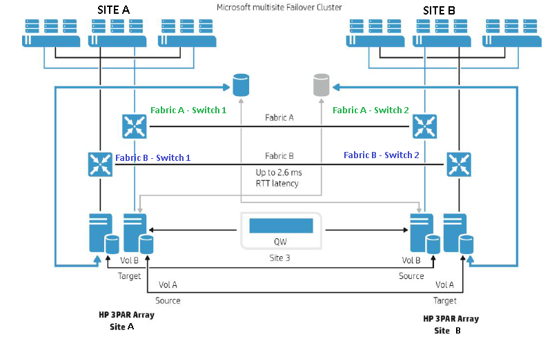
A Metro Cluster allows VMs spread across data centres to act like they are in a single local cluster. In order to allow this functionality the VMs need access to the same storage at both sites, this is achieved with products like NetApp’s Metrocluster and HPE’s Peer Persistence products which enable a single view of the storage even though it is located in a multi site configuration,this is depicted in the diagram below. Let’s dig into how this works.

Each LUN is replicated between both storage systems using synchronous replication, however only one LUN can be written to at a time, whilst the other remains in a read only mode. The writable LUN is presented out to the hosts via active paths, the read only LUN is effectively hidden by the paths to it being marked as standby. This is based on ALUA (Asymmetric Logical Unit Access), which was used in traditional storage systems like the EMC Clarion. ALUA was used to mark preferred optimized paths to the controllers owning a LUN and non optimized paths marked indicated indirect paths to the LUN. The non optimized standby paths would only become live if the primary path failed.
Below shows an example of the paths on a ESXi host connected to a Metro Cluster, the live paths are shown as active but this can be switched over using the storage array management software so that the active and standby paths reverse.

What are the requirements FOR A STRETCHED CLUSTER?
In order to setup a VMware Metro Cluster the following is required:
- VMware metro storage cluster licencing – There is no minimum license edition of vSphere for the creation of a metro cluster. However if automated workload balancing is required with DRS the minimum licence required would be Enterprise Plus edition
- Supported storage connectivity. Fibre Channel, iSCSI, NFS, and FCoE are supported
- Max latency for vMotion from vSphere 6 is 150ms
- Stretched storage network across sites
- Max supported storage replication 10ms, may be lower depending on vendor
- Suitable software options selected for storage e.g. 3PAR Peer Persistence option
- Maximum network latency RTT between sites for the VMware ESXi management networks is 10ms
- vSphere vMotion network has a redundant network link, minimum of 250Mbps.
- A third site is required for deployment of a witness which will act as an arbitrator
- Storage IO control is not supported on a Metro Cluster enabled datastore
Benefits
- Mobility – since storage and network config is shared across the sites VMotion requirements are met and VMs can be either manually migrated or dynamically balanced across the cluster and locations using DRS
- Reduce physical boundaries – DRS can be used to automatically balance workloads across locations
- Reduce downtime – A metro cluster allows the online movement of VMs and storage for planned events without downtime. These can be performed together or independently. For example if maintenance was planned on the storage system the active paths could be switched over to the other site or if the entire site was expected to be offline the storage and VMs could be migrated to the opposite site
- High availability – vMSC protects against both storage system and site failures. In the event of a storage system failure this will be detected by a witness VM and the active paths switched over to the other system and for a site failure VMware HA will restart the VMs at the surviving site
- Reduced RTO – Automated recovery reduces RTO for storage or site failure
Disadvantageous
- Complexity – Although setting up a vMSC is not too strenuous, it is certainly more complex than a single site cluster
- Testing – Although vMotion between sites and switch over of storage between sites can be tested there is no simple way to test for a full failover scenario for example with a run book
Considerations for VMware metro cluster design
- HA admission control – The first consideration around HA is a logical one and this is that you should use admission control and set it to a reservation level of 50% for CPU and memory. This is to ensure that should a failover between sites be required it will guarantee the resources are available
- HA datastore heart beating – Is used to validate the state of a host. It is important that datastores used for heart beating are configured at both locations so that false results are not received if a site is lost. It is recommended by VMware that 2 datastores are set for heart beating at each site
- HA APD – The response for an All Paths Down needs customising, you will find the setting in HA settings after selecting Protect against Storage Connectivity Loss you will then need to select Power off and restart VMs.

- ESX host names – Create a logical naming convention which will allow you to quickly identify which site a host is in. This could be the site is in the naming convention you choose or you choose a numbering system that reflects the location, for example odd hosts are in site one. This will make designing your system and running it day to day easier
- Data locality and host affinity rules – Ideally hosts should be accessing data from their local storage array to improve response time. To ensure this is the case use VMware affinity rules to define the preferred site for VMs to run from a local LUN. Do not use must rules, if you do even in the event of a site failure the VM’s will not move as it would violate the rule
- Logically name the LUN’s with their home sites – This is not a must and some may argue they want the flexibility to move LUNs between datacentres but it will make it easier for BAU staff to track which are local datastores
What causes a failover?
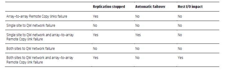
For an automated fail over of the storage to occur there are a number of failure conditions that must be met, those conditions that must be met for 3PAR are summarised in the following table from HPE.

Essentially contact needs to be lost with the storage array and replication needs to be stopped.
Testing
There is no automated testing method for a Metro Cluster however with a bit of thought it is possible to run some tests, although some are more invasive and risky than others. We will run through the tests starting with the least risky and move towards more invasive and risky
1 vMotion – This is the simplest test to move a VM between sites. Although a simple test vMotion has more requirements than HA and so will start to build confidence as we move through tests
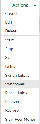
2 Storage switch over – Switching which site the storage is actively running on can again be completed online with little risk
3 Simulated storage failure – This test incurs risk since it is possible IO could be lost when the storage system is taken offline. Verify the specifics of a failover scenario with your storage vendor but for example with a 3PAR you will need to take the management network and Remote Copy network offline simultaneously. Before you complete this disable auto failover of the LUNs you do not wish to be part of the test
4 Simulated site fail over – For this test you simulate a site failure by simulating a storage failure as above plus a host failure to get HA to kick in. Choose a VM to test and move this to a host by its self, power off other VMs in the environment put the hosts out of scope into maintenance mode. Perform HA simulated failover as per https://kb.vmware.com/s/article/2056634. Again there is risk in this test, be selective about which VMs you choose to test
Remember tests 3 and 4 do incur risk, perform them at your at your own risk and only if the project requires it.
Further Reading
VMware vSphere Metro Storage Cluster Recommended Practices
The dark side of Stretched clusters
NetApp Metro Cluster tutorial video