Choosing infsight VM details option in 3PAR

Configuring 3PAR with InfoSight

HPE previously announced the availability of HPE InfoSight for 3PAR. This guest post by Armin Kerl runs through the process of setting up 3PAR Cross-stack Analytics for VMware. This allows a number of insights into the performance of VM’s held on the storage.

HPE 3PAR InfoSight PERQUISITES

Hello 3PAR Guys, today I will show you how to enable VMware integration in HPE InfoSight. Before you register your system in InfoSight you need the following prerequisites in place:

  • 3PAR Call Home enabled, as I describe here
  • An active support contract is in place, which you can verify with the HPE Warranty Checker
  • Additionally if you wish use Cross-stack Analytics for VMware  the following requirements apply:
    • Minimum 3PAR OS 3.2.2 MU4 minimum with Service Processor version 4.4 MU7 or later
    • 3PAR OS 3.3.1 with Service Processor 5.0 MU3 or later
    • 3PAR Service Processor must be configured to use the RDA Transport Agent (SSA is not supported)
    • VMware vCenter versions 5.5, 6.0 or 6.5

High-level setup steps

If the above requirements are in place you will then be able to complete the following high level steps to get InfoSight with cross-stack analytics.

  1. Register the system with InfoSight
  2. Configure VMware integration in the Service Processor
  3. Ensure that the RDA transport mode is used for the Service Processor

We will run through these steps in the next sections:

Registering system with InfoSight

  • Logon to InfoSight with your HPE passport ID
  • Click on the HPE 3PAR StoreServ / StoreOnce Register Systems link on the Welcome Page (Settings > Register Systems). It’s easiest if you create
  • You will then choose a system group you want to assign the device to.  This allows you to group all your organisations devices
  • You will then be presented with a System Group Registration Token to copy and paste onto each 3PAR to perform registration.  You will see a full set of instructions on how to do this, with the choice of doing this via CLI, SSMC and IMC.

Integrating the 3PAR Service Processor with vCentre

The exact steps you need to take will depend on the version of the Service Processor you are running. First we look at doing this with service processor 5.0.3

vCentre integration Service Processor 5.0.3

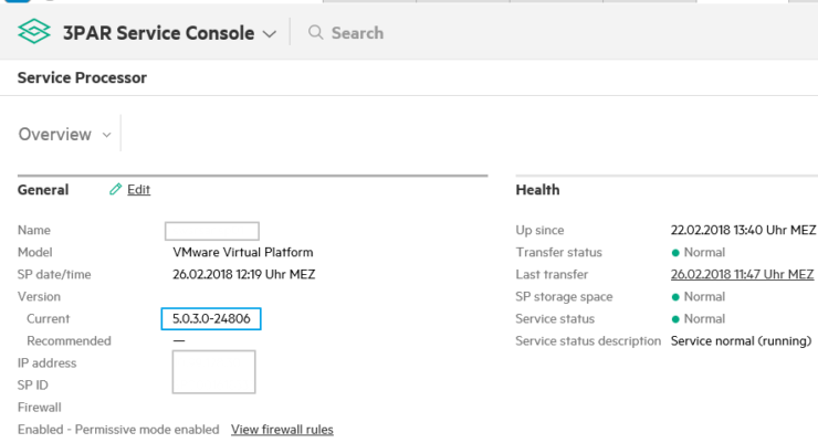
1 Once you are logged into your Service Processor you can see the firmware version of the service processor like in the screenshot below

503 error

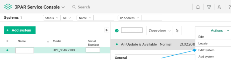
2 Now go to Systems from the main menu

3 From the Actions Menu chose Edit System

3 Choose VMware integration

Adding vCentredetails to ServiceProcessor

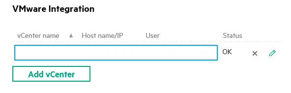
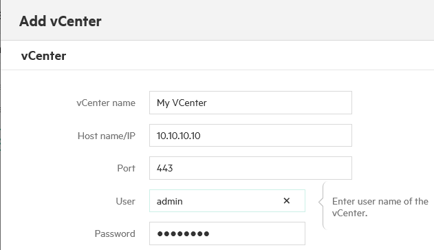
4 Choose Add vCenter. Enter IP address, password and other relevant information for your vCenter. The account supplied needs to have read only access to the vCentre

Adding vCenterto infosight

vCentre integration Service Processor 4.x

  • Login to SPOCC
  • Select SPmaint from the Main Menu and choose Option 3 “StoreServ Configuration Management”
  • Choose “Add StoreServ” then “Add vCenter”
  • Supply the required information and click add. The account supplied needs to have read only access to the vCentre

RDA transport mode

If you got this Message:

RDA Message

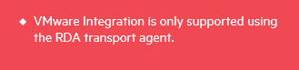
Than the RDA Transport Protocol is not active, and the SP uses the old SSA transfer agent. This happens mostly, if you have updated the Service Processor from 4.4 to 5.0. To solve this:

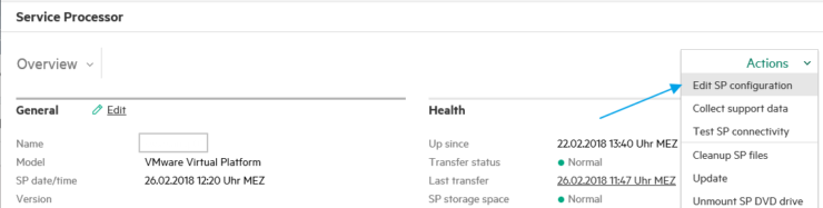
Logon to the Service Processor with the “hpepartner” Account and go to “Edit SP configuration”.

Service Processor Edit
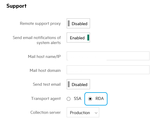
Now under Support change from SSA to RDA Transport Agent.

Check if Call Home Transfer is still working, it may be the RDA needs different firewall exceptions on your site.

Note that Service Processor 4.x releases require HPE Support to modify the configuration from Secure Service Agent (SSA) to Remote Device Access (RDA).

Checking Infosight is integrating with vCentre

The setup steps are now complete we can now check everything is working as expected.

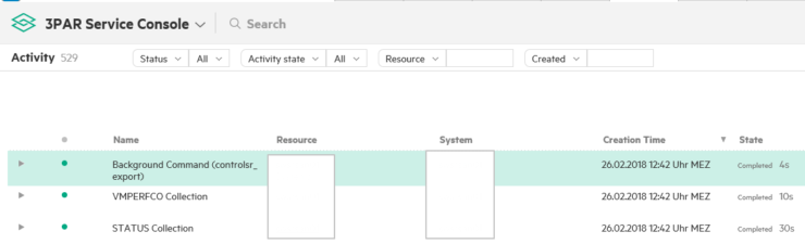
In Activity, we see now VM Collections running.

3PAR activity log

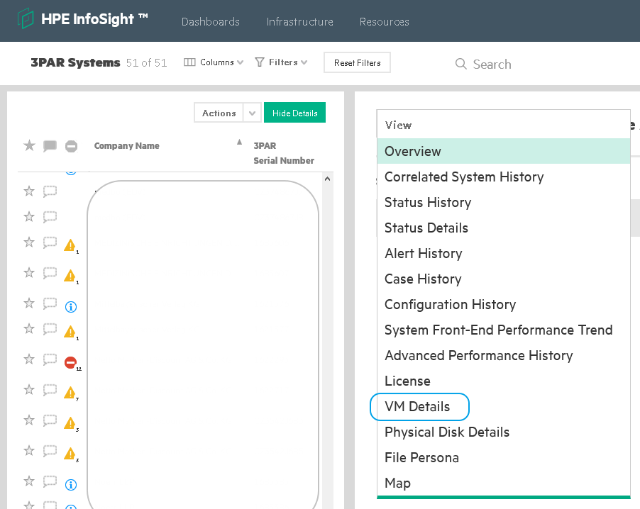
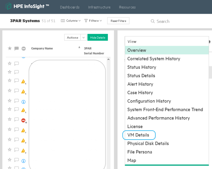
To be able to view the collected stats we need to wait 2-4 hours then log onto InfoSight and click “VM Details”:

Choosing infsight VM details option in 3PAR


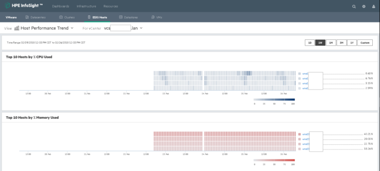
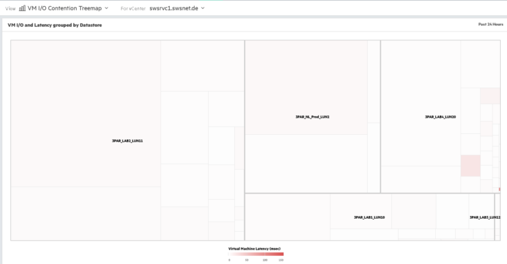
Now you get lots of VM to Storage related information:

Example 3PAR INfoSight Repor2t


Example 3PAR INfoSight Report

For further information on the setup process look at the HPE Infosight For 3PAR Quickstart Guide v1.4

In this previous post available you can see more examples other reports InfoSight will make available. That is all the steps you need to configure 3PAR with InfoSight.

Thanks to the HPE InfoSight team for reaching out with additional information to support this post.


How to rename a 3PAR Remote Copy Group

This guest post by Armin Kerl  runs you through the procedure to rename a 3PAR remote copy (RCOPY) group. The truth is, that you cannot rename them, so the correct title should be:
How to move a Volume between RCopy Groups without the need to do a full resync,
below are the steps you need to take:

1 First, create a new empty RCopy Group with the new Name (using SSMC).

2 Next we need to stop the RCopy group and unexport the volume. From the CLI stop the Old_Group:

showrcopy -d groups Old_Group

stoprcopygroup Old_Group

Unexport the Volume from Old_Group on the Secondary Site (using SSMC).

3 Having stopped the RCOPY group and unexported the volume we can remove the Volume from Old_Group but choose to keep the snapshot:

dismissrcopyvv -keepsnap Prim_Volume Old_Group

4 To avoid a full resysnc of the volume we want the new RCOPY group to use the existing snapshot. Find the newly generated snapshot name:

showvv -p -type vcopy

5 Add the Volume to the new New_Group:

admitrcopyvv Prim_Volume:sv.0.rcpy.36.264.1 New_Group Sec_3PAR:Sec_Volume.r

6 Start and check the New_Group:

startrcopygroup New_Group
showrcopy -d groups New_Group

7 If the Old_Group hasremaining Volumes, do the same:

startrcopygroup Old_Group

showrcopy -d groups Old_Group

8 Export the Volume again on the secondary 3PAR (use SSMC).

9 Finally delete the temporary Snapshot:

removevv sv.0.rcpy.36.264.1

Armin  is a regular contributor to d8taDude.com, if you would like the chance to share your experiences in front of thousands of reader check out the guest posting opportunities.


Confirm failover

3PAR Remote Failover SSMC

                  3PAR storage Remote Copy Failover, Recovery & Restore using IMC

Today we have a highly detailed guest post written by Deepak Garg covering the 3PAR remote copy failover and recovery process. If you fancy writing a guest post check out this post.

This post covers the procedure using SSMC, if you wish to read some more background on Remote Copy and using the 3PAR management console check out this previous post.

For the remote copy failover, recover and restore operation there are defined steps involved which need to followed as below.

  1. Failover
  2. Recovery
  3. Restore

Important Note

  • DR is normally done in case we are having disaster in one primary/source Data center and none of the server are accessing impacted storage which need to be used for failover.
  • In this document since we are doing the exercise with below volumes so it is assumed and also necessary that associated hosts with these LUNs are shutdown so that there is no I/O from hosts in Primary DC:
    • DR Group name: DR_Testing_RC_GRP
    • Source Volume name: test_volume_for_dr_testing
    • Destination Volume name: test_volume_for_dr_testing


Failover

a) Stop Remote Copy Group    

Reverse the role of all volume groups on the system that is still in normal operation (the failover system). Here we will consider that system “System-A” is in failed state or having some planned maintenance activity.

Below screenshot shows that how to open Remote Copy Groups from the SSMC:

Remote copy menu

Below screen shot shows the snippet we want to do the failover of replication group “DR_Testing_RC_GRP” from Source system System-A to System-B

 Left pane shows the group name and on right side we can see the source, target volume name.

Volume pairs

Below screenshot shows the state of the 3PAR remote copy (Started and working condition initially) before starting the failover:

Remote copy group

During this exercise, first of all we have to stop the remote copy replication group “DR_Testing_RC_GRP”.

Note: Before this ensure that hosts associated with Source volume are shut down and there is no I/O on the source volume otherwise data corruption may happen.

From the SSMC, click on the Action button and select Stop

Stop copy group

Stop copy group confirm

By stopping the Remote copy group below status will show in SSMC. At this point in time our Volume is still writable in System-A, until we initiate Failover.

b) Failover Remote Copy Group   

Once the remote copy group is in failed state then we will see that Group state is in Stopped state (as shown in last snippet). Now we must Click on Actions again on the failed remote copy group (in our case we are preparing example with remote copy group “DR_Testing_RC_GRP”) and click “Failover” option as shown below

Failover group


Now one pop-up window will open (as shown in next picture) and click “Failover” and after that one more pop-up will open and click “YES, Failover” here.

Note: – After this failover will be executed for the selected group. The failover operation changes the role of secondary groups on the backup system (i.e. System-B) from “Secondary” to “Primary-Rev”. Any LUNs (VLUNs) associated with the volumes in the selected groups become writable by hosts connected to the destination system (destination system is System-B in our case). These VLUNs will be in writable permission from both side 3PAR so we must ensure that no write operation on VLUN from Source site as stated in pre-requisite before failover started.

Confirm failover

Now there should be Group state as “stopped” as per below picture. Replication status in the table will be as “Stopped” and Destination system (i.e. System-B) will show its role as “Primary-Rev” with DR state as “Failover”. This also shows that now Writable LUNs are on both side system, “System-A” & “System-B” (in the “Writable LUNs” column).

At this stage Volume can be presented to host in Destination Data center from destination Storage system (System-B) and application can be started in Destination DC (assuming that Source DC is still down).

Recovery

a) Description of Recovery Option    

Recover option will recover the failed system (in our case failed system is System-A). When both systems in the remote-copy pair are ready to resume normal operation, reverse the natural direction of data flow and resynchronize the systems.

Now, we have to go on the replication group which was failed earlier (in our case it is “DR_Testing_RC_GRP”) and click Actions and then “Recover” This will copy data / initiates reverse replication and synchronize the delta changes from the reversed volume groups on the failover system (System-B) to the corresponding volume groups on the recovered system (System-A).

Once executed the role of the remote copy group on the source system (System-A) becomes “Secondary-Rev”. Also, any LUN associated with the volumes in the selected groups become non-writable on the source system (System-A).

Note: – The recovery operation can be executed only on groups that have successfully completed the failover option. LUNs on System-A will be in read-only during this time to ensure that no writes are happening on Source volume from any host and Delta are copied from target system to Source system. We also need to make sure that before starting recovery, host associated with destination volume should be shut down to ensure that there is no new writes are happening during this process.


b) Recover Remote Copy Group  

Below two pictures shows the process on how to put a replication group in recover state, Click Actions on replication group which was failover and click on the option “Recover” and then click RECOVER in pop-up window.

Recover remote copy group

Confirm recovery

Once clicked on Recover prompt, there will be one more pop-up, click Yes, recover now. Important to note that VLUNs will not be writable now on source system “System-A” and it will be in writable mode on backup system “System-B”.

Now, we should be able to see Source role for “DR_Testing_RC_GRP” on source system should be “Secondary-Rev” and “Primary-Rev” on the Destination System (System-B) as shown in below picture. Now the DR state will be in “Recover” state.

State started


Verification:

1 Issue the showrcopy command from the CLI on the failover system (System-B).Verify the following:

  • The Status of the target system (recovered system – “System-A”) is ready
  • The SyncStatus of all volumes in the Primary-Rev volume groups is Syncing.
  • The Status of all sending links is Up,

2 Issue the showrcopy command from the CLI on the recovered system (System-A) Verify the following:

  • The Status of the target system (System-B) is ready
  • The Status of all sending links is Up
  • The Role of the synchronizing volume groups is Secondary-Rev
  • The SyncStatus of all volumes in the Secondary-Rev volume groups is Syncing

Restore

a) Description 

Once the recovery is completed for the remote copy group then we must restore back the actual state of replication group. i.e. bring the replication group (in our case it is “DR_Testing_RC_GRP”) back to “System-A” as primary role and again replication from the source system (System-A) to destination system (System-B).

b) Procedure to Implement

For doing this click Actions on the replication group and click “Restore”. This restore operation restores replication for the selected Remote Copy group to a pre-failover state after the recovery operation has been completed. Once the Restore operation is executed the role of the remote copy group on source system (System-A) will be “primary” and the Remote copy group on the Destination system will be “Secondary”. Also, any LUNs associated with the volumes in the selected groups become writable by hosts connected to the source system (i.e. System-A) and become non-writable by hosts connected to the destination system (i.e. System-B)

To restore the operation back to “actual” status below pictures shows the steps:

Restore


And once we will click on the OK in the above pasted picture, then there will be one more pop-up to click Yes or No, we have to click “Yes” to complete the process.

Confirm Restore

Now the system should be able to see the status of restored replication group as it was in actual state. Below picture shows the actual status with System-A system as Source and normal state and replication pointing from System-A to System-B.

At this point servers can be started in source system to start the application.

Remote copy state

Though we have restored the Remote copy operation to original but still we should start the Remote copy group for regular sync-up using below options:


Continue running from DR

These are combination of one DR recovery in which we don’t want to bring back delta from the DR site to primary site

For Failover refer section (as described above) Option 1-3 (Failover, Recovery, Restore) and follow the same steps as upto steps Failover Remote Copy Group.

 After the above steps are covered we performed “Recovery” in previous procedure however now we will perform “Revert Failover” where delta of data changes on Target system will not be reverted to Source system.

Note: –Revert Failover” operation can be executed only on groups that have successfully completed the failover option. We need to make sure that before starting “Revert Failover”, host associated with destination volume should be shut down to ensure that there is no new writes are happening during this process

To initiate the “Revert failover” from the “Failover” state, click on Actions and then “Revert Failover” option.

Recover groupConfirm revert failover

Once we click the “Yes, revert failover” option then system will come back into same condition as initial state